|
|
|
 |
SA&N Features and Construction
The SA&N
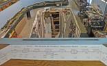
is one of the largest indoor model Railroads in Texas. THE FIRST PLAN: During 2001, we developed construction and operations standards and a mainline track and isle plan to accommodate prototypical “operating sessions” and member “fun run” sessions (members can run their personal equipment without disturbing museum cars and locos). Construction of the layout began in January 2002.
|
  |
LAYOUT MANAGEMENT COMMITTEE (LMC): The 10 member LMC oversees layout construction, project funding, adherence to standards and operation of the layout at its monthly meetings.
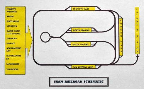
GEOGRAPHIC DESIGN CONCEPT: A hidden Houston and Corpus Christi
Division “staging yard” brings trains from below the railroad up to
the visible SA&N San Antonio Division where it follows a fictional
path between San Antonio and Fort Worth. From San Antonio to New
Braunfels, the SA&N shares trackage with the MKT and MOPAC RRs
before heading North West thru spectacular “Hill Country” scenery.
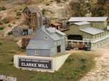
The SA&N interchanges with the Santa Fe RR West of Waco at Clarke
Center before turning toward Ft Worth. A hidden staging division
goes North from Fort Worth to St Louis. |
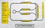 |
LAYOUT DESIGN CONCEPT: The SA&N is A “point-to-point” design with hidden north, south and mid “staging yards” to allow operation of trains on and off the modeled San Antonio and Fort Worth division. Staging yards have a loop to turn a train for a return trip or to send it on a repeat of its last journey |
 |
 |
 |
|
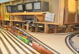 |
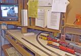
FUN RUN FACILITIES: SAMRA members bring trains from home setting them up on a yard in the rear between San Antonio and Fort Worth. This “Fun Run” yard also turns the entire layout into a giant loop for public shows and member “Fun Run” days. STAGING YARD MONITORING: The rear yard area also serves as the entry point for the North and South hidden staging yards with television monitoring of trains moving up and down from the two staging yards below. |
 |
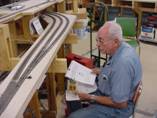
DIGITAL COMMAND CONTROL (DCC) STANDARD: Only “DDC decoder” equipped locomotives run on the SA&N. Older “DC” non-decoder equipment cannot be run on the layout LOCO PROGRAMING STATION: The rear area also houses a dedicated JMRI computer based system for programming “DCC decoder” equipped locomotives. |
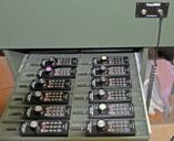 |
DCC SYSTEM: A CVP Products, “Easy DCC” system is used to control locomotives on the railroad. Wireless throttles are used for road trains with tethered throttles used in yards. The system runs all brands of locomotive decoders. Operators are encouraged to program the locomotive number itself as its ”DCC address.” Conflicting duplicate address numbers are changed on a “first come” basis and permanent multiple locomotive “consists” are assigned a number from an official log. |
 |
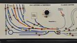
DISPATCHER: From the rear balcony, a “Dispatcher” controls train movements and communicates with the operating crews, using a magnetic rout schematic board, a telephone system and train crew “call me” lights. |
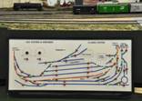 |
CONTROL PANELS—EASY TO USE: Control panels at each town feature blue on white color with the mainline shown in red. Operators simply trace their desired rout pushing each button they encounter in the direction they want to travel. Pushing the buttons “throws” all required turnouts and lights green LEDs to display the selected rout. Panels also contain a telephone, a “call the dispatcher” light and uncoupling magnet controls. Panels are hinged to allow maintenance access. |
 |
MAGNETIC UNCOUPLING: The SA&N standard coupler is the KD magnetic. Permanent uncoupling magnets are used in “spurs” while electro magnets are used on main and thru sidings. Magnet locations are marked with paint on the side of the rail and are shown on Control Panels. A number is also shown for electro magnets. Operators activate them by dialing a knob to the desired number and pushing a button that temporarily activates the selected magnet. |
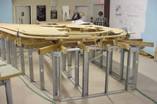 |
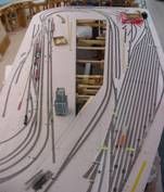
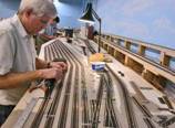
BENCHWORK: Both Wood and metal “Stud wall Benchwork” provides extra strength and allows for lower wall treatment to use any standard home construction wall material. Masonite is used for Fascia which holds “stair” rail hand bars, control panel boxes, phones, DCC plugs and holders. |
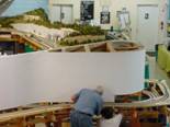 |
BACKDROP CONSTRUCTION: A coat of plaster was applied to fill cracks over Cinder block exterior walls. Interior backdrops are sheetrock with curved sections made with Luan Plywood “door skins” and 4’x8’ styrene plastic sheet. All joints were smoothed with standard floater’s plaster. |
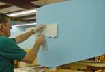 |
BACKDROP PAINTING: All backdrops are “base coat” painted with Sherwin Williams “Bonnet Blue” flat latex paint. A combination of brush painting and spray painting using New London Industries stencils and “The Sky’s The Limit” video techniques are used to apply the clouds and foreground rock and foliage. |
 |
TRACK: Code 83 rail is painted to look rusty and sun bleached. Number 8 “DCC friendly” turnouts are used on Main passing sidings with number 6 turnouts used in most other locations. 98% of track is commercial products with some hand laid track or turnouts used where necessary. |
 |
ELECTRICAL: Layout track is divided into several “power districts” so short circuits only stop the trains in its district. Low voltage electricity for the locomotives motors and a carrier signal for their DCC decoder are sent together on a 12 gauge “bus” wire below the layout. Every 3’ the track is connected to the bus wire with “drops” to prevent voltage drop. |
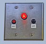 |
OTHER POWER SUPPLIES: Under the layout there are also power supplies to run the DCC equipment, turnout motors, electro magnets, telephones, control panel LED lights, television monitor cameras, and to power many tiny building and street lights. FIRE PREVENTION CIRCUIT: With so many electrical items, every 110 volt item is simultaneously turned on / off by SAMRA’s unique “Harold Scott” relay system. A red light by the exit door is a signal that the layout must be turned off before closing the building. |
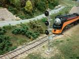 |
SIGNALING AND TRAIN DETECTION: Lighted “signal heads” are installed as part of the scenery construction. “Long range” plans include wiring them to an electronic train detection and signaling system. A “test” area will be installed prior to total commitment to a system. |
 |
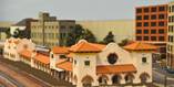
TRACTION LINE: The Texas Electric Trolley line between The SP and Pearl Brewery is also modeled and interchanges near the Sunset Station as did the prototype. |